고정 헤더 영역
상세 컨텐츠
본문
Inspiration:So I'm looking at making a small msp430fr5739 based board. I was thinking that I would be able to use the msp430 launchpad to program them. However, I hit a snag in that they don't seem to recognize the msp430fr5739 as a valid device.
I can use my FRAM boards to program them but not the $10 launchpad. Then there was all the hubbub about the new msp430g2955 chips and it got me thinking.
Why should I let Texas Instruments determine how I program my chips?Investigation:I got to looking at BSL and then got discouraged trying to find a client that works on windows, linux and OSX. It mostly seemed like it was going to be a hassle. Then I got to thinking about just using GDB and its Remote Serial Protocol. If you use msp430-gdb and mspdebug, you use this interface over a local server socket. However, an often unnoticed feature of this protocol is that it can also be used with a regular serial port.Solution:I decided to implement a gdb stub server that you load once on your msp430 chip. You can think of it as a bootloader that happpens to use the Remote Serial Protocol.
This allows you to load new programs on that chip without the need for a launchpad or an FET. All you need is a usb-serial port dongle. You can find these on ebay from $2-$10. They all go faster than the 9600 baud the virtual serial port the msp430 launchpad provides. It is likely you probably have one of these already. This scheme doesn't allow you to debug using msp430-gdb, but it does provide a way to load new code without having to deal with BSL or having to write any host side code.How it works:This version targets the msp430g2553 so that people can easily try it out. I'm guessing that most people don't have an msp430fr5739.
Msp430 Serial Bootloader Update
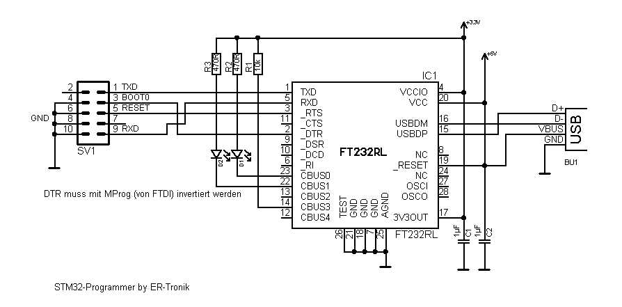
Load the attached code below to an msp430g2553 using your launchpad one time. At this point, you could remove that chip from your launchpad and throw it on a breadboard. You just need power, the caps and a pull up resistor. Then connect TX and RX to a serial to USB converter (ftdi, cp102, pl2303hx, etc.).
For simplicity, we can just test with the launchpad itself and ignore the fact that there is an FET on the board and just use /dev/ttyACM0 or COM1: on windows.At reset time, the code looks at the state of the P1.3 button on the msp430g2553. If you are holding it down, the code starts a gdb bootload/server running on the msp430g2553. On your linux box, just start up msp430-gdb to connect to the chip over a serial port. You can't debug, but what you can do is erase your flash and load a new program.
The gdb server code sits at memory 0xfa00 - 0xfdff so you do lose some of your flash.I've done some optimization see later posts in this thread.Loadable hex file:The gdbbootloader.hex file from the zip file must be loaded on an msp430g2553. I'll post code and support for other chips at a later date. I'm excited about this concept and wanted to let people try it out.To load the gdbstub firmware ( do this one time )$ mspdebug rf2500 'prog gdbbootloader.hex'MSPDebug version 0.21 - debugging tool for MSP430 MCUsCopyright (C) 2009-2012 Daniel Beer This is free software; see the source for copying conditions. Great work.not sure about the fr5739, but for g2553, there is already a factory installed BSL somewhere (0x0c00?), it should be possible to do something similar (i.e. Programming via uart). I read in a TI forum thread that the tx / rx pins used for BSL is different from the usual setup and that limits usability.i have not used it before so i don't know the difference between that and the solution u are presenting. I did examine the flash segment as i was trying to 'claim' the space for my use.

Msp430 Custom Bootloader Example
Which turns out to be unsuccessful. I don't think those segments are different, but may be there is a lock somewhere.
I would imagine whoever design it would leave a way to update the BSL code, or may be not.anyway it would be interesting to see if it actually works or not. I read in a TI forum thread that the tx / rx pins used for BSL is different from the usual setup and that limits usability.Originally, this is what I was thinking of doing. However I'm going to target the larger chips, so the amount of memory used by this won't really be signficant.The reason I decided to do this over BSL was its simplicity. With BSL you need to twiddle the Test/Reset/BSL TX/ BSL RX. That means I have to write custom host code, or find a bsl loader program. I have to figure out which pins are BSL/TX/RX, I have to make sure the usb device I'm using supports the ability to toggling the DTR/CTS pins at the right time.
The other way I've seen people implement bsl loading, is with a launchpad that is acting as a bridge. I think that is TI's published solution. However you are wasting a launchpad and a chip to do this and you still have to make sure the circuit on the target device isn't affected by the BSL setup.With this solution I don't need a smart dongle. In fact using the virtual serial port of the msp430 launchpad proves that point.: )You can even use this with a wireless serial dongle. There is no flow control to worry about really.-rick. I would imagine whoever design it would leave a way to update the BSL code, or may be not.On the msp430f4/5/6xxxx series you can replace the BSL code with your own.
With the msp430f2xxx/gxxxx it is ROM based and there isn't a way to replace it. I think the msp430fr5xxxx can be replaced, and I'll probably look into that too.
However, if that msp430fr59xx stuff appears I'll probably not bother.This solution can really be thought of as a gdb bootloader. The big advantage to this solution is that you can download precompiled binaries of msp430-gdb for windows, linux and osx.
Once you have downloaded a binary, you get the incredible power of gdb for free. It can examine, disassemble, write to flash, erase, save a chunk of memory to a file. Basically you get a lot of functionality without doing anything.With BSL, what I found was a lot of different tools and none that work on all 3 platforms.
Maybe there is a universal BSL tool, but I didnt' find it, which is how I ended up with this solution.-rick. Inspiration:So I'm looking at making a small msp430fr5739 based board. I was thinking that I would be able to use the msp430 launchpad to program them. However, I hit a snag in that they don't seem to recognize the msp430fr5739 as a valid device.
I can use my FRAM boards to program them but not the $10 launchpad. Then there was all the hubbub about the new msp430g2955 chips and it got me thinking. Why should I let Texas Instruments determine how I program my chips?I've been using the msp430 launchpad to program msp430fr5739 with the usual SBW. I had to get a newer mspdebug than ubuntu has because it was trying to erase the FRAM (and failing). I wonder why it wasn't working for you.
Bootloader System Block Diagram. Communication Channel: File I/O or any other means to read the Application File. File Reader: A reader which reads the Application File. Flash Programming: to program the Application. Vector Redirection: To switch between the Bootloader and Application Vector Table. User Interface: Showing status and information to the user, and to switch between application and bootloader mode at system startup.Processor Expert comes with Flash Programming and Communication components (USB, SCI, I2C, ) installed. I have a user interface already, plus an file reader component created.

Combining this with my other components should enable me to make a bootloader:-). Flash Memory of the BootloaderTo make sure the bootloader gets linked only into its space, I reduce the FLASH memory for it. With the settings below I limit the FLASH memory from 0x0000 (vector table) up to 0x3FFF.
Msp430 Serial Bootloader Code

That means my application memory area starts at 0x4000.So I change the available flash for the bootloader in the CPU properties, and cut the available FLASH size on the KL25Z128 from 0x1FBF0 (128 KByte) in the Build Options tab to 0x3FB0. FRDM-KL25Z with Bootloader Switch BoardYou might wonder why I have to initialize it, as this is usually done automatically by PElowlevelinit in main?
The reasons is: I need to do this.before. main gets called, very early in the startup code. And that’s the reason as well why I need to set the SIMSCGC5 register on Kinetis to clock the peripheral.Inside the CPU component properties, there is a Build option setting where I can add my own code to be inserted as part of the system startup.


